Emulsion channels are what some would call the black magic of a carburetor - what happens here can be explained in several ways. The simplest illustration would be to imagine the fuel curve being moved up or down by the size of the main jet, and then the tilt or angle of the fuel curve being moved by the emulsion package. Many things go into the tuning the emulsion of a carburetor, which includes the high-speed air bleed (which supplies air to the emulsion orifices), the emulsion orifice size, number of orifices, and event he float level.
The hole size of each orifice is very critical in that the size of the hole will ultimately determine ho much air is to enter the main well - larger holes will yield leaner numbers. Going too far from a normal setting could cause you to adjust your jet size in order to maintain the car's behaviour - be sure to document or graph your adjustments and always note your baseline. Our carburetors and block kits offer a wide range of adjustability to help you reach your results. Pre-drilled and blank restrictions are available for tuning.
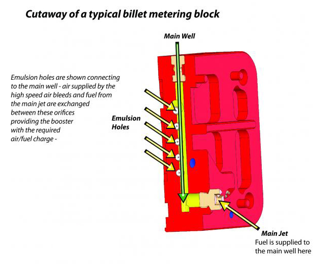
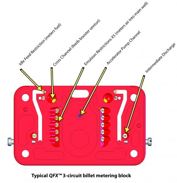
Shown Below is a typical billet metering block, seen from the side that mates to the main body. This particular model does not utilise a power valve, nor does it have a place to do so - essentially, it is a race-only calibration. From this side, you can visually locate all of the tuneable orifices including emulsion, idle feed restriction, and intermediate discharge.
- Idle feed restriction controls the amount of fuel that mixes with the air from the idle air bleed. Decrease the orifice size to lean out the idle mixture - increase it to richen the mix.
- Intermediate discharge controls the amount of fuel/air mixture that is supplied to the intermediate pull-over tubes located in the main body.
- Emulsion orifices control how much air (supplied from the high-speed air bleed) is allowed to enter the main well of the metering block and ultimately feed the booster venturi.
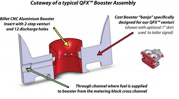
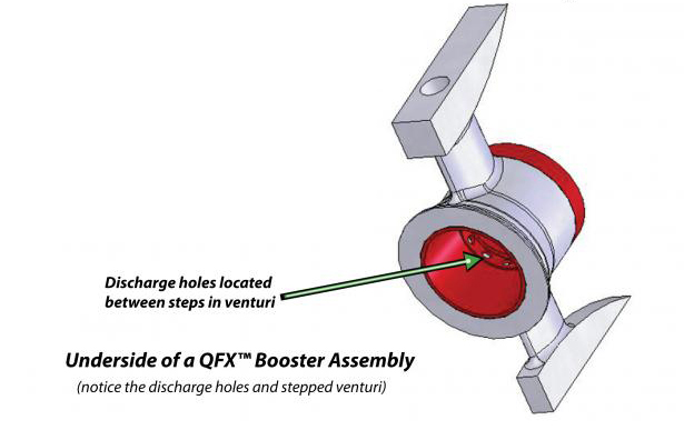
Boosters are one of the most critical areas of a carburetor in terms of performance. Everything done to tune an engine is dependent on the correct booster and how well it is matched to the application. Annular boosters are found on every style of carburetor we make, and proper research should be done to determine your specific needs. Annular boosters employ several small holes to discharge the air/fuel mixture into the venturi, whereas all other types of boosters (i.e downleg, straight) use one hole. Think of the difference between the boosters the same as the difference between a water hose and a shower head. Annular boosters provide better fuel atomiztion and can increase power and torque, depending on your application. The emphasis here is that not all applications will see a benefit from an annular booster.
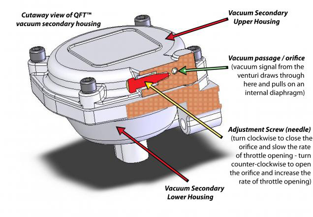
Vacuum secondary carburetors operate based on the amount of vacuum, or draw that is "sensed" by the carburetor. Most vacuum secondary carburetors (QFT included) have a small hole in one of the primary venturi - this hole is extremely vital to the secondary's operation. As you increase the amount of throttle, the air speed in the venturi increases. As the air rushes past the aforementioned hole, "draw" or vacuum is produced. This draw will pull on the internal diaphragm of the vacuum secondary housing, causing it to open the secondary throttle shaft. Most vacuum secondary carburetors determine the rate of opening with different spring tensions - to change the rate you have to disassemble the housing and change the spring. A QFT carburetor is much more sophisticated, and simply requires a standard screwdriver to change the rate of opening. If you would like your secondaries to come in a little quicker, simply turn the screw counter-clockwise. This opens up an orifice to increase airflow and speed up the process. We recommend when turning the screw in either direction to turn no more than a 1/4 turn at a time until you are satisfied.
If the secondaries seem unresponsive or do not work, double-check that the orifice supplying draw is clear, and that the diaphragm is sealed properly and not torn.
The baseline setting on most of our carburetors is 1.5 turns off of the seat.
